Glory Info About How To Build An Alarm Circuit
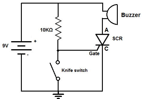
How To Build A Door Alarm Circuit
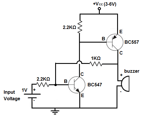
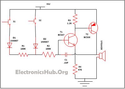
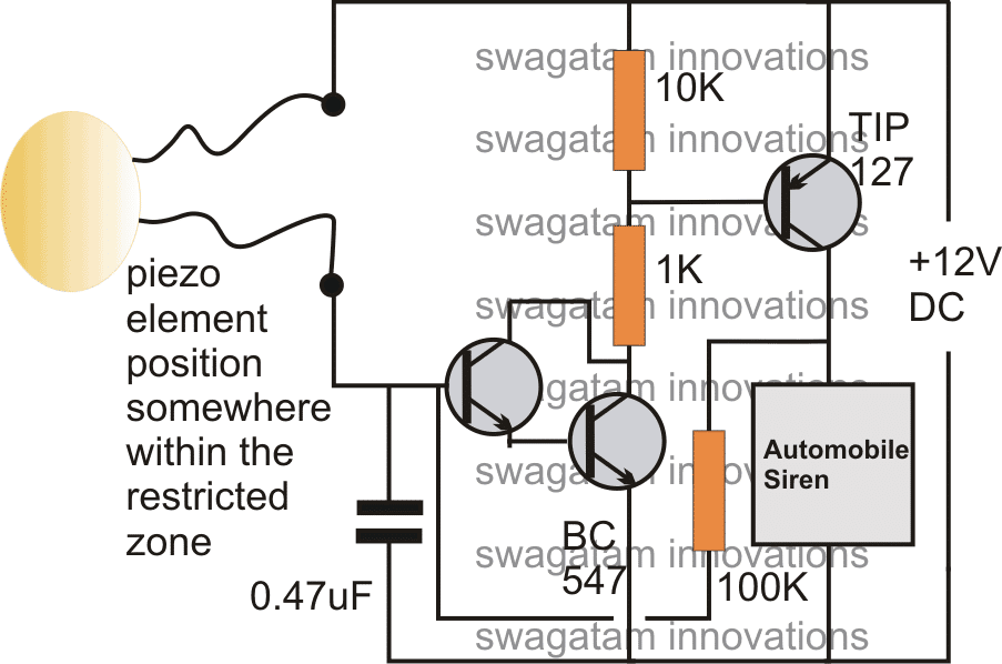
How To Build An Alarm Circuit With Transistors
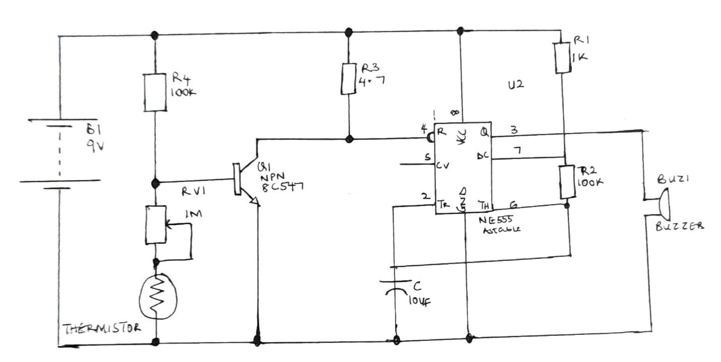
Alarm Circuit: The Construction And Working Principle
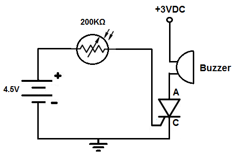
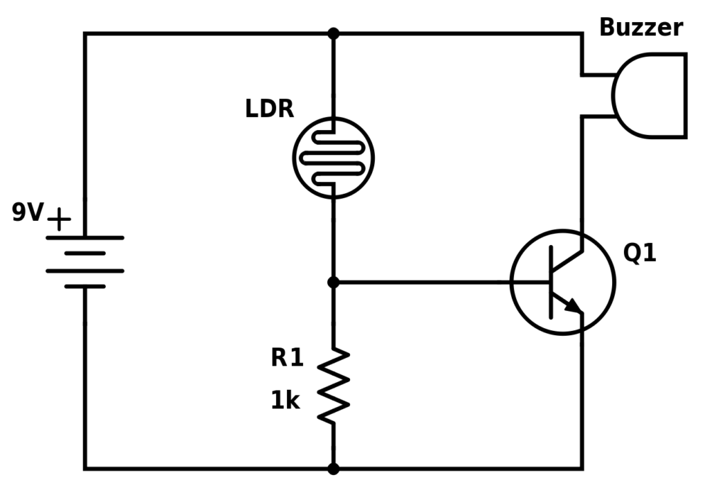
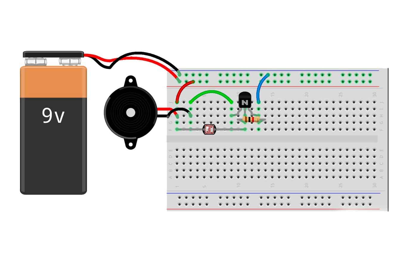
How To Build A Light Alarm Circuit
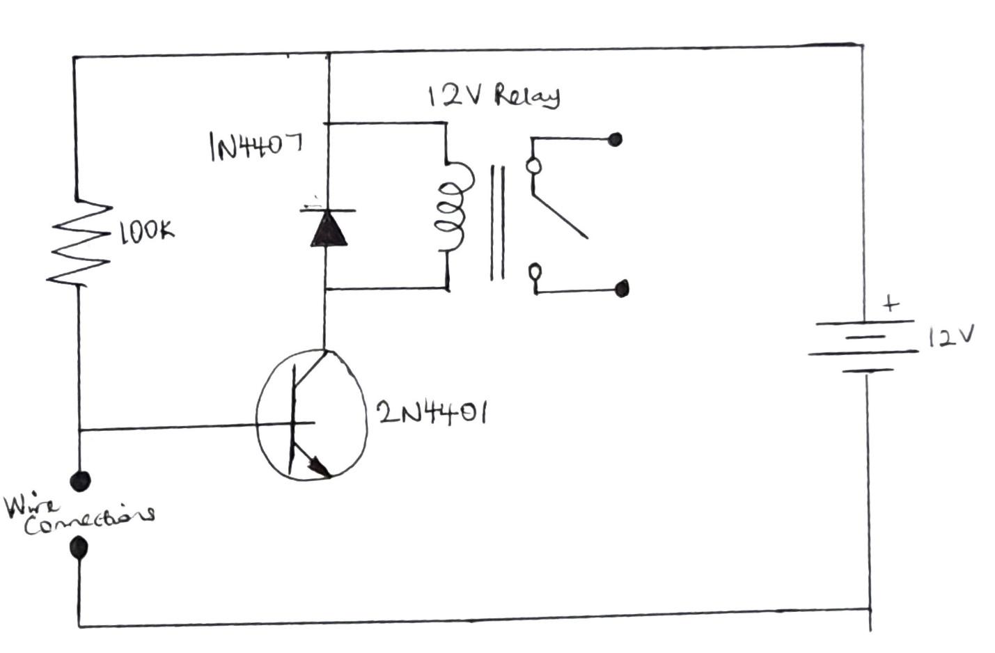
Simple Security Alarm Circuit Working And Applications
The Sunrise Wake-up Alarm - Build Electronic Circuits
Take a veroboard and rub its side with the copper.
How to build an alarm circuit. The schematic for the door alarm circuit is shown below: These two work together to create the desired detection. The first block of code chooses the pin for the buzzer, which is pin 12.
This video explains how series and parallel circuits are assembled based on the diagrams in the guide. This electric circuit design comprises two major parts, which are the sensor and trigger. Simple timer circuit using ic 4060.
If (value == high) digitalwrite(buzzerpin, high); Higher variable output voltage from ic 7812. How an alarm circuit works.
In this fire alarm circuit, we are using the ntc thermistor, as the temperature increases, the thermistor’s resistance decreases, and current flows to the circuit. Another method to increase the range is to use a series photodiode. In this video i am going to show how to make simple security alarm circuit using 12v relaysecurity alarm system component required:1) 12v relay2) 12v led o.
Pir solar home lighting circuit. The second line chooses the pin for the input pin, which represents.
Alarm Circuit: The Construction And Working Principle
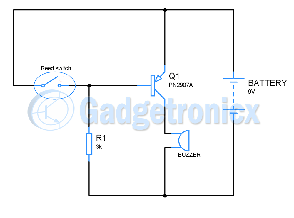
Thief/ Door Alarm Using A Transistor - Gadgetronicx

Simple Door Alarm Circuit | Make Very Easy - Youtube

9 Burglar Alarm Circuit Ideas | Electronics Projects Circuits
5 Simple Alarm Circuits For Protecting Your Home/office From Theft | Homemade Circuit Projects

Burglar Alarm Circuit - Electronics Projects
The Sunrise Wake-up Alarm - Build Electronic Circuits

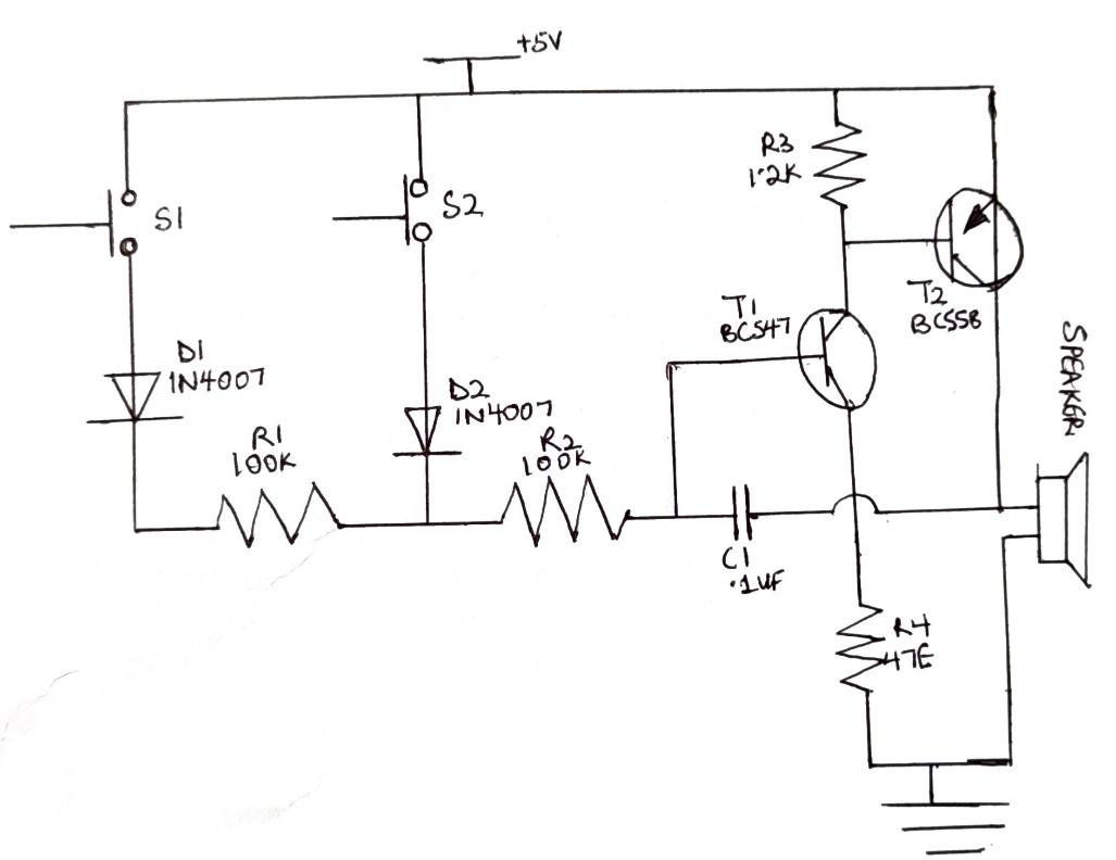
Simple Touch Alarm Circuit
Simplest Theft Alarm Circuit - Gadgetronicx

How To Make Basic Alarm Circuits And Control Circuits?
Alarm Circuit: The Construction And Working Principle
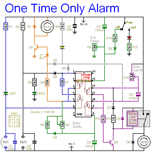
How To Build A One-time-only >> Burglar Alarm Circuit Under Repository- Circuits -54853- : Next.gr

Simple Burglar Alarm With Transistor 2n4401
